
Content
A purchase order goes out for "16 mm round bar, one end threaded, 4.8 m long". The bars arrive, the clevises do not fit the thread, and once the turnbuckles are wound fully in, every rod turns out 30 mm short. That sequence is the everyday reality of the bracing rod trade: the steel is rarely the problem, the interfaces are.
Rod bracing is one of the least glamorous parts of a structural package, yet it determines whether a portal frame stays square, whether a pipe rack takes wind without racking, and whether a canopy moves the way the model said it would. Getting it right is a matter of a few specifiable numbers.
Direct answer: a bracing rod is a tension-only member, so its capacity is set by the threaded root section, not by the bar diameter. Its real-world behaviour is set by the end fittings, the take-up available in the turnbuckle, and the corrosion protection on the threads. Three lines in a specification — stress area, take-up allowance, coating class — prevent most field failures.
Under wind or seismic action a rectangular bay wants to become a parallelogram. In an X-braced bay, one diagonal lengthens and goes slack while the other shortens and is pulled tight, transporting the lateral shear down to the foundations. The rod never resists compression: reverse the load and the opposite rod takes over. That single behaviour explains most of the design and sourcing rules that follow.
A single rod cannot brace a joint against reversed load, because it buckles the moment the force flips. Practical solutions use at least two rods per braced bay, or one rod plus a compression strut. When a drawing shows a lone diagonal without a companion, it is worth asking which direction the design wind comes from.
A fully threaded bar is convenient, but the tensile stress area is smaller than the nominal shank. An M16 coarse thread gives roughly 157 mm² against a nominal 201 mm², about 22 percent less. On a grade 8.8 bar at 640 MPa yield, that puts the yield load near 100 kN and a working tension near 60 kN. If a design calls for 70 kN, a heavier bar or a higher grade is needed — the nominal diameter alone tells you nothing.
Clevises, pin eyes, gusset plates, stub anchors and turnbuckle bodies all sit in the same load path and are usually made from different materials, in different factories, to different coatings. A hot-dip galvanised turnbuckle mated to a black oxide rod guarantees a corrosion cell at the first thread. Matching finish across the whole assembly is cheaper than repairing it later.
Capacity
Read the stress area, not the nominal diameter. A 20 percent reduction is normal on a rolled thread.
Slenderness
Tension members are commonly checked against an L/r limit of about 300 to control sag and vibration.
Take-up
Aim for at least 25 mm of usable thread travel at each end, beyond the calculated stretch.
Protection
Hot-dip galvanising to ISO 1461 typically delivers 70–85 µm locally on bar over 6 mm thick.
The reason rod bracing persists is mass. A 16 mm bar weighs about 1.58 kg per metre; a 50×50×5 angle of comparable tensile capacity weighs 3.77 kg per metre and is far harder to handle at height. The comparison below puts the options side by side on the criteria that actually drive a purchase decision.
Where a frame genuinely needs compression capacity — a braced bay in a seismic zone, for example — rod bracing stops being the right answer regardless of cost. Where the case is wind only, the rod wins on handling, freight and the size of the connection plates.
Designers rarely check how much a rod will stretch between the slack condition and the working tension. That number governs how much adjustment the turnbuckle has to absorb, and it is not the same across diameters. The chart shows the elastic elongation of a 6 m rod pulled to 15 kN, assuming E = 205 GPa.
12.5 mm
3.6 mm
16 mm
2.2 mm
20 mm
1.4 mm
24 mm
1.0 mm
The practical reading is that a stiff, large-diameter rod has very little give, so a cut-length error translates almost one-for-one into a slack or over-tightened brace. A slimmer rod is more forgiving to install but needs a wider take-up window. As a rule of thumb, budget the turnbuckle travel as the calculated stretch, plus the permitted cut-length tolerance, plus about 10 mm of residual thread so the brace can still be adjusted after the structure has settled.
One further consequence: rods are tightened by rotation, so the thread must be clean and lubricated or the friction will consume most of the torque before any tension reaches the bar. Dry, galvanised threads routinely need 30 to 40 percent more torque for the same tension, which is why site teams end up over-tightening and stripping the turnbuckle body.
Order patterns from a fastener manufacturer give a rough sense of where these parts end up. The split below reflects how tonnage is typically distributed across applications; it is an indicative picture, not a market study.
The retrofit slice is worth noting. Older frames are frequently re-braced after a change of use, and there the rod is chosen for its tolerance of imperfect geometry rather than its strength. A rod with 50 mm of spare take-up is often more valuable on a retrofit than one with an extra 10 kN of capacity.
The specification process is short if it is done in the right order. Each step below closes off a failure mode that recurs often enough to be predictable.
Fix the load path first. Confirm the design tension per brace, whether the load is reversible, and how many rods share the bay. A single rod in a reversible-load bay is a detailing error, not a procurement choice.
Size on stress area. Convert the required tension into a stress area, then a nominal diameter. Allow for the thread reduction of roughly 20 to 25 percent and check the clevis and pin against the same number.
Choose the grade against the environment. Plain carbon steel covers indoor and dry service. For elevated-temperature or pressure-boundary work, ASTM A193 B7 chromoly is the usual reference; for low-temperature service, ASTM A320 L7 provides the impact toughness. Stainless 304 or 316 is reserved for genuinely aggressive atmospheres, because the cost jump is steep.
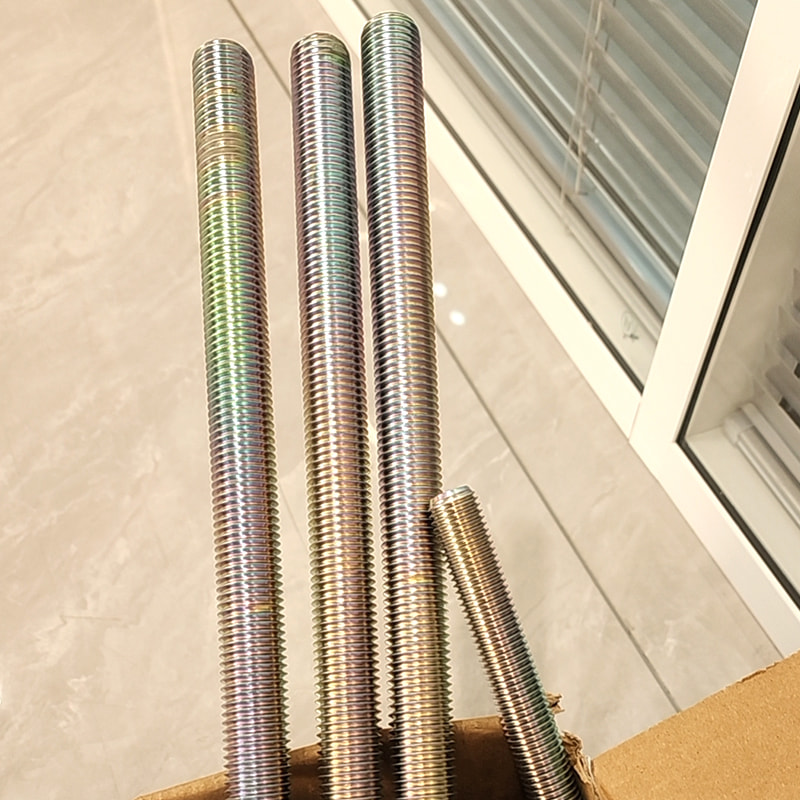 ASTM A193 B7 Alloy Steel Threaded RodsHigh-strength B7 chromoly rods for elevated-temperature or pressure-boundary service, available in zinc-plated, black oxide, or hot-dip galvanized finishes.View Product →
Decide the thread form and coating together. Rolled threads are stronger and cheaper to produce than cut threads and are the default for a fully threaded rod. Hot-dip galvanising adds 70 to 85 microns and interferes with fine thread fit, so either over-tap the nuts or specify a coating that does not build up, such as zinc flake.
 ASTM A320 L7 Full Threaded BarL7 alloy steel full threaded bar for offshore service, available in HDG, zinc, or black oxide; confirm finished cut length and clean chamfered ends.View Product →
Agree the cut length and the ends. State the finished centre-to-centre length with the turnbuckle at mid-travel, not the bar length. Chamfer the cut ends so the thread starts cleanly, and confirm the clevis jaw width matches the gusset plate thickness.
Ask for the paperwork. A tensile test on the finished bar, a coating thickness reading and an EN 10204 3.1 certificate are the three documents that resolve most disputes. If the lengths are non-standard, custom and OEM/ODM production is normally cheaper than buying stock bar and machining it on site.
Stock lengths in B7 and L7 alloy steel, and in plain carbon steel 8.8 grade, cover most of what a bracing package needs; the variable is usually the cut length and the surface finish rather than the material itself.
 Grade 8.8 Carbon Steel Full Threaded BarM16×300 plain carbon steel bracing rod in 8.8 grade, with galvanized or black finish; stock lengths suit bracing packages where cut length and finish vary.View Product →
A bracing rod assembled and tensioned correctly on day one can still be load-free two years later. The checks that matter are simple and mostly visual.
None of this is exotic engineering. The bracing rod is a simple, efficient, tension-only element, and it stays reliable when the stress area, the take-up allowance and the coating are all specified explicitly rather than inferred from a catalogue photo. The failures that do occur almost always trace back to one of those three numbers being left to the shop floor.
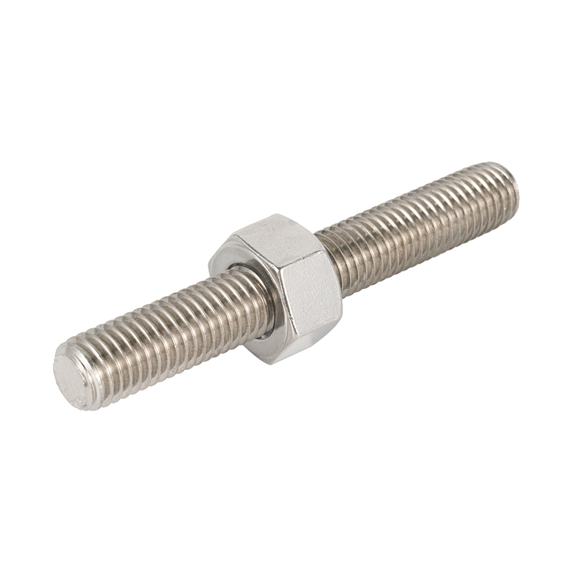 M10×300 Carbon Steel Grade 8.8 Galvanized Fully Threaded Rods
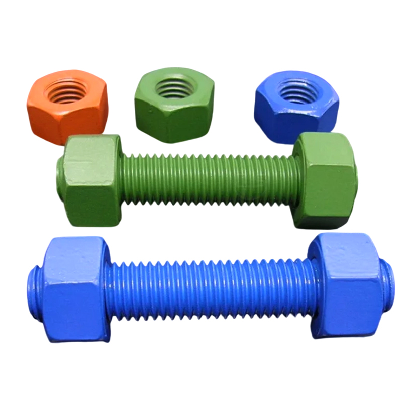 Alloy Steel M27*300 PTFE / Dacromet Coating B7 Threaded Rods Studs
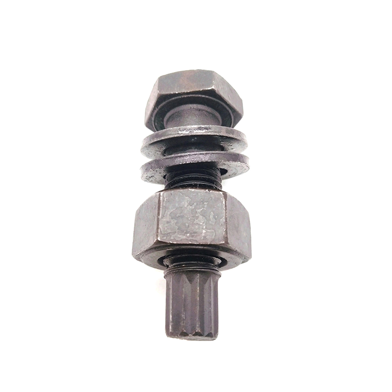 M24*200 Alloy Steel High-Strength Bolts for Steel Structure
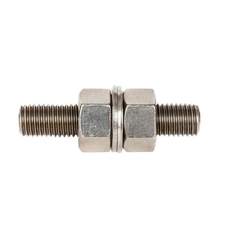 1-8 UNC *5" Alloy Steel ASTM A193 B7 Threaded Rods Grade L7 Threaded Studs
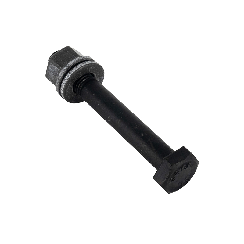 Steel Structure M20*120 Zinc Plated High-Strength Bolts
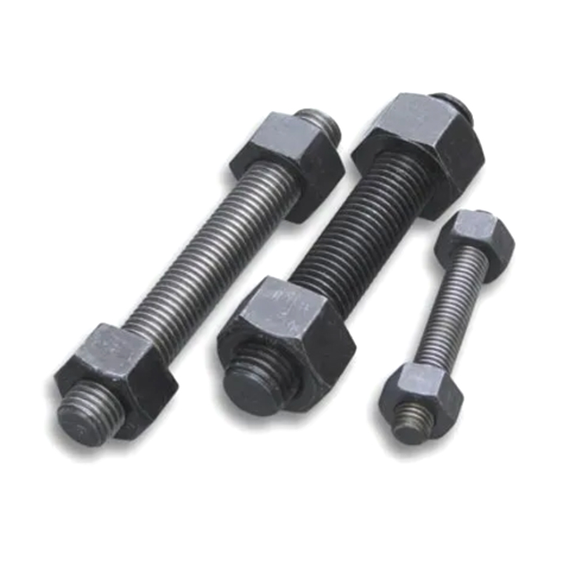 1-8 UNC *5" Alloy Steel ASTM A193 B7 Threaded Rods
 Contact Information
 Address


 中文简体
 Português
 Español
 Deutsch
 русский
 عربى