
Content
A Cylinder Head Bolt Does Not Simply Hold the Head Down—It Is a Calibrated Spring
The primary function of a cylinder head bolt is not merely to clamp the head to the block. It is to maintain a precise, uniform clamping force across the entire head gasket sealing surface under conditions of extreme thermal cycling, cylinder pressure spikes, and material expansion differentials. When torqued correctly, the bolt stretches elastically into a state of engineered tension, behaving as a high-strength spring that stores over 8,000 to 12,000 pounds of clamping force per fastener. This stored energy compresses the head gasket sufficiently to seal combustion pressures that can exceed 1,500 psi in a forced-induction engine, while simultaneously sealing high-pressure oil galleries and coolant passages that run between the head and block. A bolt that has yielded, fatigued, or been installed with inadequate preload cannot maintain this seal when the cylinder head and block expand at different rates during warm-up. Understanding that a head bolt is a dynamic, spring-loaded clamping device—not a static threaded pin—is the foundation of every correct installation and diagnosis procedure.
Cylinder head bolts fall into two mutually exclusive categories, and treating one like the other causes immediate engine failure. Standard bolts are torqued within their elastic range, meaning they return to their original length when loosened and can, in many cases, be reused if they meet dimensional inspection criteria. Torque-to-yield bolts are tightened beyond their elastic limit into the plastic deformation zone, where the material permanently stretches and does not return to its original length. The TTY approach provides more consistent clamping force because the bolt's load curve flattens in the plastic region—small variations in turn angle produce minimal variation in clamp load, making the process more repeatable on an assembly line. The irreversible trade-off is that a TTY bolt has been stretched past its yield point and must never be reused. A second torque sequence on a yielded bolt will push it further into plastic deformation until it necking-fails, often snapping during final torque or, worse, days after the engine returns to service.
A manufacturer's service manual provides the definitive classification, but physical indicators include a torque specification that lists an initial torque value followed by an angle-based final step such as 90 degrees or 180 degrees. This angle specification, rather than a final torque number, is the hallmark of the TTY procedure because the bolt is being turned a measured rotation into its plastic region. Standard reusable bolts are specified with a final torque value in Newton-meters or foot-pounds, with no angle step, or with an angle step that remains within the elastic range and is explicitly noted as reusable in the service literature.
The tightening sequence cast into every cylinder head is not a suggestion—it is a stress-distribution map. Cylinder heads are not infinitely stiff; they flex micro-inches under bolt tension. If bolts are tightened from one end to the other, the head warps into a slight wedge shape, concentrating the clamping force at the last-tightened corner and leaving the starting end under-compressed. The spiral pattern starting from the center and working outward in incremental torque steps gradually pulls the head down evenly, allowing the gasket to compress uniformly and the head to settle parallel to the block deck. A typical procedure involves three to five progressive torque passes: an initial low-torque pass to seat all fasteners, intermediate passes at increasing torque values, and a final angle sweep for TTY fasteners. Skipping a pass or consolidating steps puts the gasket under uneven compression during the critical initial crush phase, and the resulting seal inconsistency may not reveal itself until the engine reaches operating temperature and the unevenly loaded fire ring gives way.
A torque wrench measures friction, not clamping force. Of the torque applied to a head bolt, approximately 50% overcomes friction under the bolt head, 40% overcomes thread friction, and only 10% to 15% actually generates the clamping preload. If the threads in the block are corroded, dirty, or damaged, the torque wrench clicks at the specified value while the actual bolt stretch—and therefore the clamping force—falls dramatically short. A bolt torqued to specification on dirty threads may deliver less than half the designed clamping force, while the same torque on threads lubricated with an unapproved compound can over-stretch the bolt past yield. This is why every manufacturer specification includes a thread condition requirement: clean, chase the threads with a bottoming tap if necessary, and use only the specified lubricant—whether that is clean engine oil, a specific assembly lube, or dry threads. The lubricant type changes the friction coefficient, and the torque specification was developed for that specific coefficient. Substituting a molybdenum-disulfide assembly lube on threads specified for engine oil can reduce friction so dramatically that the bolt yields before the target torque is reached.
Cylinder head bolt failures are rarely spontaneous—they follow predictable patterns with identifiable causes. Understanding these patterns allows a technician to diagnose the failure rather than simply replacing the bolt and hoping the problem does not recur.
A bolt that snaps at the junction of the shank and the head flange has been over-torqued, either through a TTY bolt being reused, incorrect torque specification application, or thread lubrication mismatch. The fracture surface typically shows a classic cup-and-cone ductile failure with necking reduction visible on the shank diameter. The fix is procedural: new bolts, verified torque specification, and correct thread preparation.
A bolt that fractures in the threaded section or mid-shank with a flat, beach-marked fracture surface has failed from cyclic fatigue. This indicates the bolt was not achieving sufficient preload to keep the joint closed under cylinder pressure. Each combustion cycle pried the head slightly away from the block, cyclically loading the bolt until it cracked. The root cause is chronic under-torque, often from dirty threads, a failing torque wrench, or a stretched TTY bolt reused.
High-strength fasteners above roughly 36 HRC hardness are susceptible to hydrogen embrittlement, where atomic hydrogen diffuses into the steel grain structure and causes brittle intergranular fracture. The failure often occurs hours or days after installation, with the bolt snapping at rest. The source is typically acidic chemical exposure during manufacturing or cleaning, or corrosive combustion byproducts in a head gasket breach. The fracture surface appears granular and intergranular under magnification, without the ductile deformation of an overload failure.
| Failure Mode | Fracture Appearance | Primary Cause | Prevention |
|---|---|---|---|
| Ductile Overload | Cup-and-cone, necked shank | Over-torque or reused TTY bolt | New bolts, correct torque spec |
| Fatigue | Flat, beach marks, no necking | Insufficient preload, cyclic loading | Clean threads, calibrated wrench |
| Hydrogen Embrittlement | Granular, intergranular, brittle | Hydrogen ingress, high hardness | Source from certified suppliers |
| Corrosion Pitting | Pitted surface, reduced cross-section | Coolant leak into bolt bore | Seal bolt threads, replace gasket |
Head bolt holes in the block are blind bores that can trap oil, coolant, or cleaning solvent. When a bolt is threaded into a fluid-filled blind hole, the fluid becomes trapped beneath the bolt and cannot compress. As the bolt advances, hydraulic pressure builds in the trapped volume. This pressure can exert enough force to crack the cast iron or aluminum block at the base of the bore, a catastrophic and often non-repairable failure. The prevention is absolute: every blind bolt hole must be thoroughly cleaned with compressed air and a suitable solvent, then inspected with a borescope or probe before bolt installation. Thread chasing with a bottoming tap followed by solvent flushing and air drying is the minimum procedure. Even a few drops of residual oil can crack a block when a bolt is driven to final torque. This step is not optional and is one of the most common causes of block damage during head gasket replacement.
Modern engines pair aluminum cylinder heads with cast iron or aluminum blocks, creating a material mismatch that cylinder head bolts must accommodate. Aluminum expands at roughly twice the rate of cast iron—approximately 23 x 10⁻⁶ per degree Celsius versus 11 x 10⁻⁶. When an aluminum head on an iron block heats from ambient to operating temperature, the head grows more than the block, increasing the clamp load on the bolts. The bolts must be designed with sufficient elastic stretch range to absorb this differential expansion without yielding. In engines with aluminum blocks and aluminum heads, the expansion rates are matched, but the lower modulus of aluminum means the threaded bores are more susceptible to galling and thread pull-out. Many aluminum-block engines specify torque-to-yield bolts specifically because the consistent clamp load of TTY installation provides a margin of safety against the lower thread strength of the aluminum parent material.
For high-performance applications where cylinder pressures exceed the original design envelope, head studs replace head bolts as the clamping solution. A stud is threaded into the block finger-tight and secured with a nut on top, eliminating the combined torsional and tensile stress that a bolt experiences during tightening. A bolt must simultaneously twist and stretch as it is torqued; a stud is loaded purely in tension when the nut is tightened, producing more consistent clamp load and reducing the risk of thread galling in the block. High-performance studs are manufactured from materials such as H11 tool steel or custom-specified 8740 chromoly with tensile strengths exceeding 190,000 psi, significantly above OEM bolt grades. The installation procedure for studs differs from bolts: the stud is installed with minimal torque into clean threads, often with a thread-locking compound on the block side, and the nut is torqued with the manufacturer's specified assembly lubricant on the threads and the nut flange. The torque specification for a stud and nut assembly is different from a bolt specification and must be taken from the stud manufacturer's data, not the OEM manual.
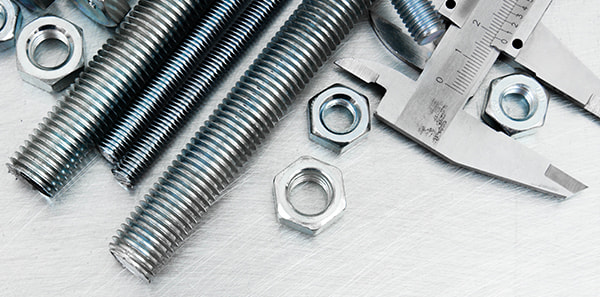
When a manufacturer permits reuse of standard cylinder head bolts, the bolts must pass a dimensional inspection before returning to service. The critical measurements are overall length compared to the specification, shank diameter at multiple points along the unthreaded section, and thread condition under magnification. A bolt that has permanently stretched will measure longer than specification and its shank diameter will be reduced in the stretched region. Any necking, no matter how subtle, disqualifies the bolt. Threads must be inspected for galling, corrosion pitting, and crest deformation. A bolt with damaged threads will produce inaccurate torque readings and inconsistent clamp load. If any bolt in a set fails inspection, the entire set should be replaced—mixing new and used bolts on the same cylinder head creates an uneven clamping force distribution that compromises head gasket sealing.
Cylinder head bolts must be installed on a completely cold engine. The torque specifications and angle measurements in the service manual are calibrated for ambient temperature, typically 20°C to 25°C (68°F to 77°F). An engine that is even warm to the touch has expanded, and the thermal expansion changes the friction conditions and dimensional relationships that the specification assumes. A bolt torqued on a warm engine will be under-torqued when the engine returns to ambient temperature. The resulting clamp load deficiency may not cause immediate failure, but it reduces the margin against head gasket blowout, particularly under high-load conditions. The engine should sit overnight or for a minimum of several hours until all components are at stable room temperature before the final torque sequence is performed.
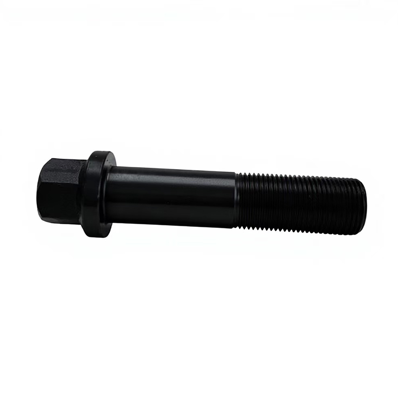
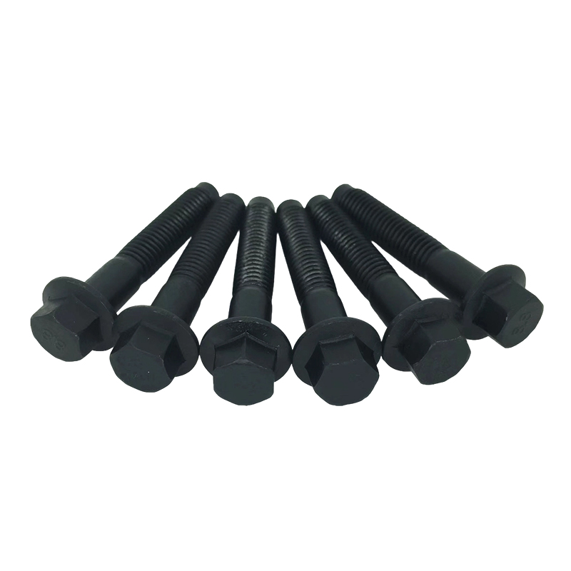
 M8×40 Carbon Steel Grade 8.8 Black Cylinder Head Flange Bolts
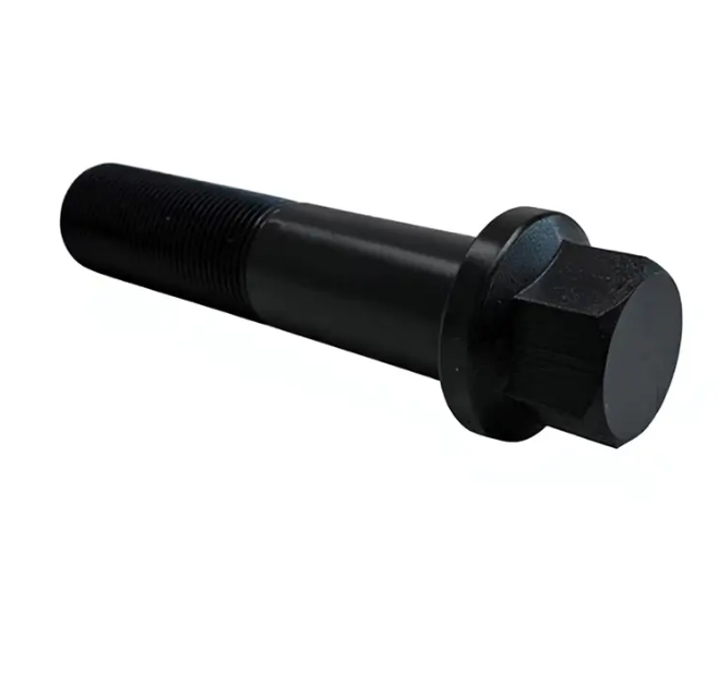
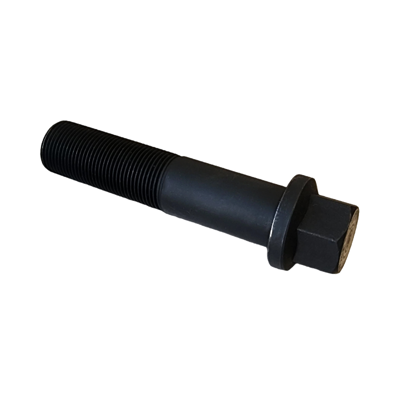
 M8×60 Alloy Steel Grade 8.8 Zinc-Plated Hex Head Flange Bolt Cylinder Bolts
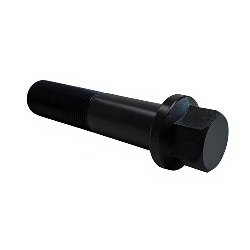
 M8×100 Alloy Steel Grade 8.8 Phosphate Coated Cylinder Hex Head Flange Bolts
 M5*10 Grade 8.8 Carbon Steel Flanged Hex Head Bolts
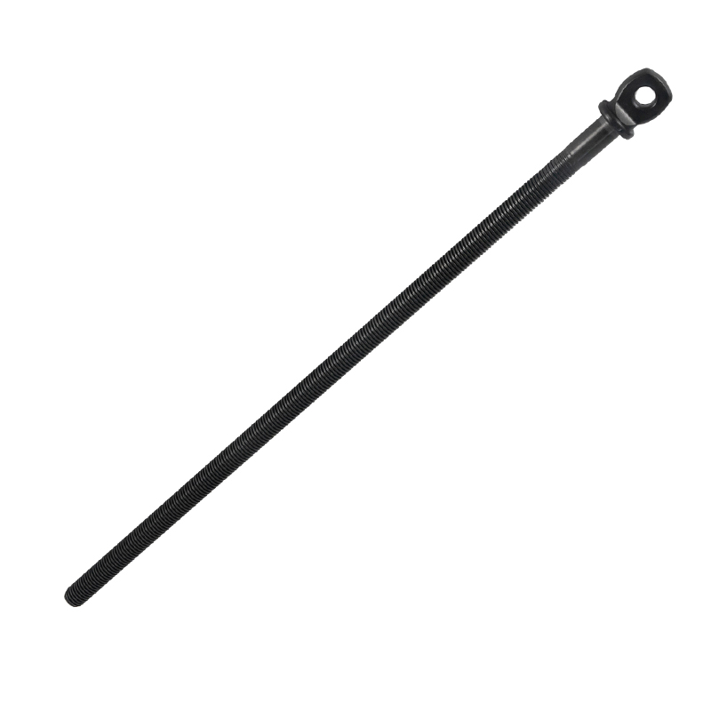 Flat Head Jack Screw Rods
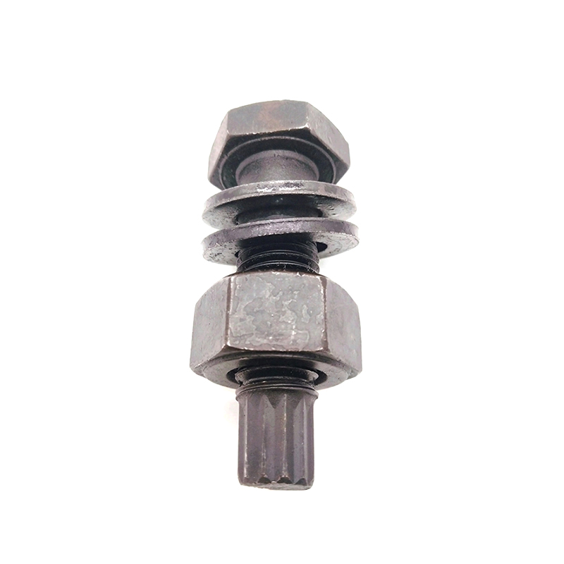 M24*200 Alloy Steel High-Strength Bolts for Steel Structure
 Contact Information
 Address


 中文简体
中文简体 Português
 Español
 Deutsch
 русский
 عربى
عربى
